What is Multisim?
Multisim is a SPICE based, electronic schematic capture and simulate program provided by National Instruments.
Multisim is part of a suite of Printed Circuit Board (PCB) design software, called the Circuit Design Suite, which also includes Ultiboard - a PCB layout tool.
Circuit designers draw their Multisim schematic by choosing from an extensive library of analogue, digital, hybrid and power components, which they then connect up using "virtual wires". Each component is comprised of detailed SPICE simulation parmeters, which allow the device to behave like real hardware, i.e. as if connected on a breadboard. The designer can then choose a simulation method to test how the device behaves in the connected circuit configuration. It is always a good idea to simulate a new design, before breadboarding or prototyping, to reduce the amount of rework required.
Multisim provides a variety of simulation options: DC operating point, AC single frequency, AC and DC sweeps, transient and noise analyses, and many more. SPICE component models include manufacturer specific devices (e.g. LM741, PIC16F84, etc.) and "virtual" perfect components. More advanced users can create their own component models, or edit those already in the libraries. A variety of instruments, such as voltmeters, ammeters, wattmeters, oscilloscopes, Bode plotters, etc. can be connected to the circuit outputs to provide instant measurement of parameters during and after simulation. These instruments can be virtual "perfect" instruments, with editable settings and parameters, or can be chosen from a library of instruments which mimic specific manufacturer types, e.g Agilent, Hewlett-Packard, etc.
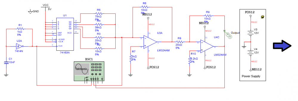
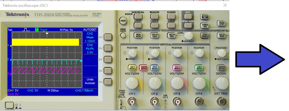
xxAxonite (2017). Pixabay CC0
As well as allowing hierarchical design for better readability, Multisim seamlessly integrates with Ultiboard, passing physical component parameters such as shape, size, and pinout. This allows the PCB designer to layout their board to specified parameters such as board area, track thickness, size of vias, materials used, etc., giving them options of auto-tracking or manually tracking the copper, electrical connections. Checking against the schematic can be done, and the finished board layout can be exported as Gerber files, for a PCB manufacturer to build.
Accessing Multisim
Multisim is free to Science, Technology, Engineering and Mathematics (STEM) students, and can be downloaded from Multisim 14.2.0 Education
First, create a National Instruments account, using your student credentials, at NI Create Account, and log in. You can then download the software at Multisim 14.2.0 Education. Once downloaded, the NI Package Manager will start automatically and will guide you through the installation process.
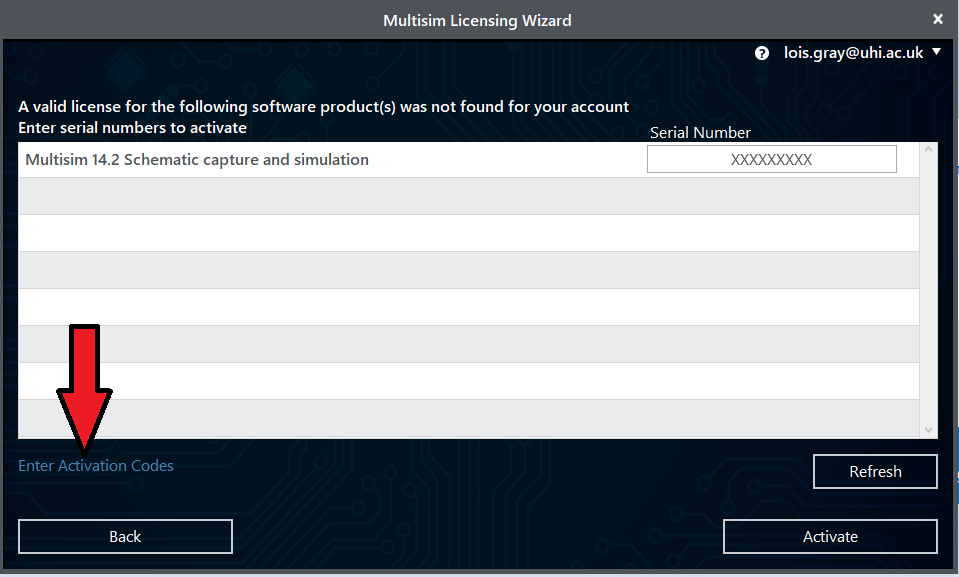
Once installed, you will need to activate the product by obtaining a serial number from UHI Unidesk. Then, the first time you try run Multisim, the licensing wizard will appear: Click Activate and enter your serial number.
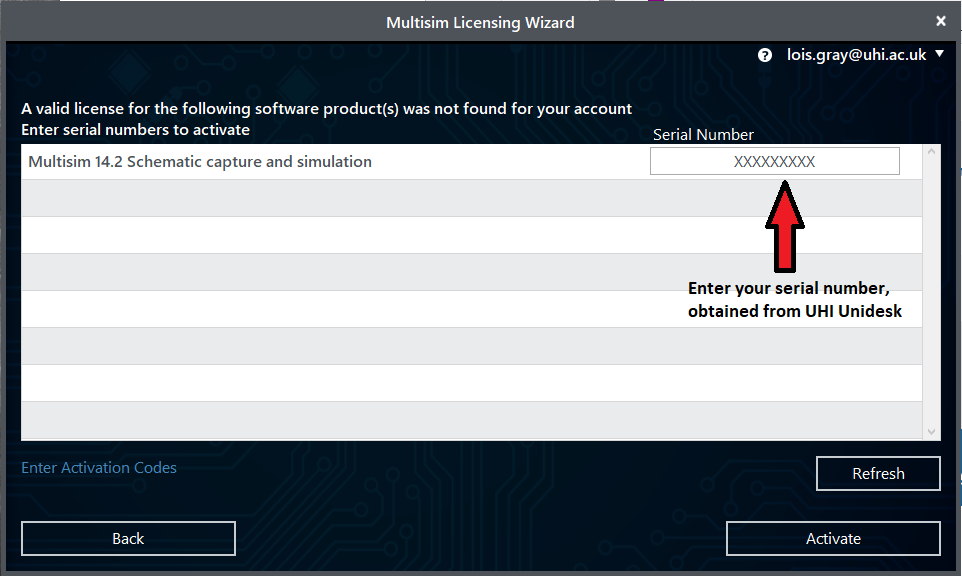
What you will need
1. Internet access with reasonable speed for downloads.
2. Your student email address.
3. Admin rights to install, on your computer.
4. 6 MB of free hard disk space on your computer.
National Instruments will then email you with an Activation Code, which you should enter by clicking the Enter Activation Codes box.
Blank space
Blank space
Click Apply Codes then Launch and Multisim is ready to run from either your Start Menu, or an icon on your desktop.
If you have problems installing Multisim, please contact UHI Unidesk.B
There is also a reduced functionality, live online version of Multisim at Multisim Online. It can only run simple voltage and current simulations. Here is a 12 minute video on how to use Multisim Online to build an inverting Op Amp:
UHI
Other Options for Circuit Simulation
1. Multisim for students can be bought at Studica.
2. Multisim can evaluated free for 30 days by clicking the Evaluate button in the Multisim Licensing Wizard.
3. LTSpice is an alternative industry standard, available for download at Analog Devices LTSpice.
4. Tinkercad is an online circuit simulator for schools. It can be accessed at Autodesk Tinkercad.
Learning Resources
The most comprehensive way to learn Multisim, is to work through the tutorials provided by National Instruments:
1. Introduction to Multisim: Learn to Capture, Simulate, and Layout in Less Than 30 Minutes at Introduction to Multisim.
2. Explore Circuit Behavior Using Simulation-Driven Instruments in NI Multisim at Using Simulation-Driven Instruments.
3. Spice Analysis Fundamentals at SPICE Analysis Fundamentals.
If you want a quick start introduction you can watch this 14 minute video, on how to build and test an inverting op-amp circuit:
National Instruments also provide a plethora of Multisim training materials, including videos, notes, examples, and application notes, at National Instruments Multisim.
There are, of course, many YouTube videos demonstrating various uses of Multisim. Here are two good ones covering more advanced use:
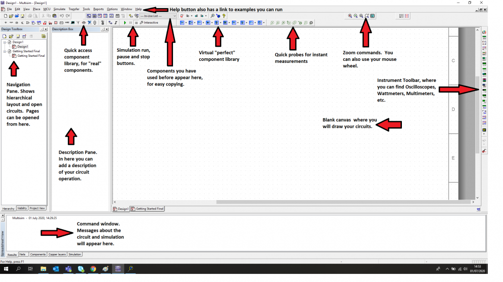
Multisim Layout
Multisim Examples
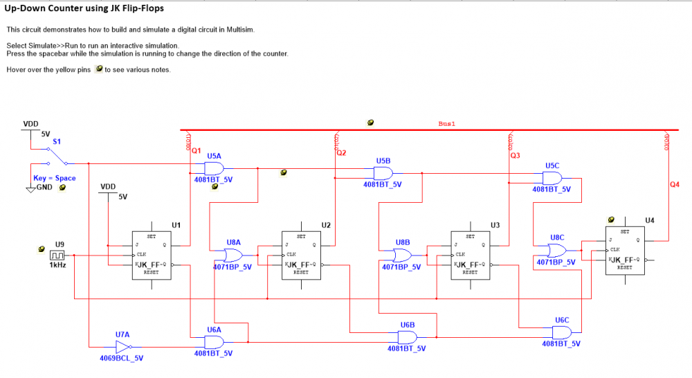
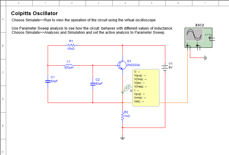
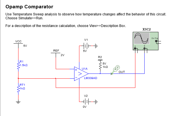
Here are some examples which you can open (and simulate) from the Multisim Help: Find Examples button.
A) PowerSupply.ms14. From Analog menu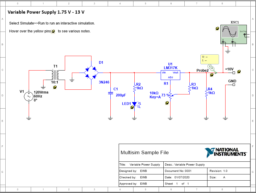
C) Up-Down Counter.ms14 from Digital menu
B) Colpitts Oscillator.ms14 from Parameter Sweep Analysis
D) Temperature Sweep - Comparator.ms14 from Temperature Sweep Analysis menu
Step Through Multisim
Here is a step through the inverting op amp schematic simulation, shown in the video on page 4.
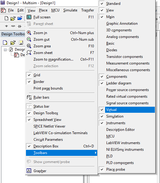
Step 1: Opening the Virtual Toolbar
When you first run Multisim, you will see the User Interface. The first step is to open the Virtual Toolbar from View: Toolbars: Virtual
Step 2: Placing Components
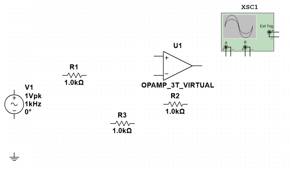
Now select "perfect" components (by left mouse clicking) from the Virtual Toolbar and place them on your blank canvas. You can also select more realistic components from Place: Components menu which opens an extensive, searchable library of components, grouped according to their function (e.g. Transistor, Diode, Analog, Misc Digital, etc.). The ones we are using from the Virtual Toolbar are:
Signal Source Family: Place AC Voltage Source
Analog Family: Place Virtual 3-Terminal Opamp. Note that Multisim automatically applies the DC voltages to the amp. You don't need to add them, although if you want to, you can use a 5-Terminal Opamp.
Basic Family: Place Virtual Resistor (3 of these, or you can get them from the In-Use-List, after you have placed the first)
Power Source Family: Place Ground. Note that all Multisim circuits need a ground. If you don't include a ground, the circuit might still run, but you will get an error message.
Instruments Panel: Oscilloscope. We are just using the two terminal virtual one, but there is also a four terminal oscilloscope and Agilent and Tektronix versions which look and behave more like real oscilloscopes.
Step 3: Editing Components
We are now going to edit the value of the bias resistor, R3, so that it is the parallel combination of R1 and R2 = 500 ohms. We do this by double left clicking on the component and typing in the new value. Multisim will accept letters for pico (p), nano (n), micro (u), milli (m), kilo (k), Mega (M), etc. You also have the option to change the component's label, so rename the component as RB.
Multisim allows editing of many of the component's parameters, such as temperature co-efficient, tolerance, etc. and advanced users can create their own components or edit library values, but we won't do this in this tutorial.
The component can also be replaced with another, and if they are pin compatible (e.g. replacing a two terminal resistor with a two terminal inductor) the new component will keep any connections you have made.
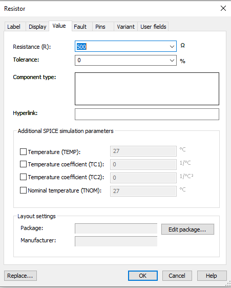
Once you have finished editing click OK to return to the canvas.
We will now rotate the component. This is done by selecting (left click) then right clicking on the component and selecting Rotate 90o clockwise (or anticlockwise).
You will see lots of other options for moving components: clicking and dragging, flipping horizontally or vertically, etc.
Step 4: Connecting Components
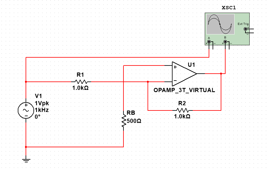
To connect components, hover over the component terminal until the cursor changes to a crosshair, then left click to select, release the left click, and drag the wire to where you want to terminate it. Left click again, and a succesful termination will show a red wire. Wire up the whole circuit as shown.
Hints
Corners can be created by left clicking while dragging.
Components and wires can be deleted while selected.
Components and wires can be dragged while selected.
Multisim will automatically tidy up connections.
Crossing points won't connect unless you left click.
Junction connections can be added from Place menu.
Now the two wires going to the Scope are both coloured red. This will make it difficult to see which is the input and which is the output, so it's a good idea to colour code these (this is particularly useful when wiring up digital circuits, as colour coding bistable outputs Q and /Q with different shades of the same colour, make fault-finding much easier). To change a wire colour, left click to select the wire, then right click to get the menu and pick Segment Colour. Select a colour which will show up on a black background, for example green.
It's a good idea to save your design regularly to a folder where you can find it again. Use meaningful names without spaces or unusual characters.
Step 5: Simulating
The last step in the process is to simulate your circuit. Multisim will tell you, in the bottom window, if you have made any connection errors, but you also need to have a good idea of what you expect to see, because Multisim won't tell you if your circuit is working but not doing what it should. For example if you have wired up a high pass filter, when you really want a low pass filter, Multisim won't flag any errors, but your circuit won't work. This is an important point, often misunderstood.
Simulating the circuit is very easy. Just press the run ( ) button. The circuit will continue simulating until you press Pause ( || )or Stop (). Instruments are opened by double left clicking them, although probes, voltmeters and ammeters will show changing values as the simulation runs.
Most instruments will have similar controls as their hardware equivalents. This tutorial doesn't go into the detailed operation of instruments because there are too many to describe, but hopefully you will recognise most of the controls from previous studies.
Probes can be connected by just selecting them and dragging them to the wires. Interestingly, current probes don't require the wire to be disconnected to allow current to flow through them. Try adding some probes to your circuit and watch the values change when you simulate.
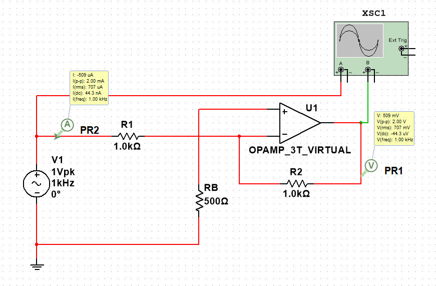
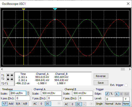
You can see from the Scope plot that this circuit is working as a perfect inverting amplifier, as expected. The output (green signal) is the same 1 Vpk amplitude as the input, with the same frequency (1kHz), but 180 degrees out of phase.
Summary
We hope you have found this introduction to Multisim useful. We have only touched on the capabilties of this schematic capture and simulation tool, with barely a mention of the many analyses it is capable of. Simulation is an incredibly useful process for electronics design: it allows quick and easy checking of circuit designs and provides the ability to make changes much more easily than can be done with hardware (breadboarding or prototyping). Of course, remember that each simulation is only as good as the data entered, so a good understanding of what you expect your design to do is required, before you simulate it.
Although Multisim is a very powerful tool, it can be used for checking simple designs quite easily. In conjunction with this teaching resource, the best way to learn to use it is to try it yourself - run some of the examples, build and test some simple circuits, try a variety of components, instruments, probes, etc.


